It’s been over a year since we’ve had a new Dropkicker review. This is partially due to a number of other projects that have taken precedence, but it’s also due to the relative lack of high-profile projects with questionable degrees of polish. Recently, I came across an opportunity to actually purchase one of the products I’ve reviewed, so I thought I would “come out of retirement” to present a special teardown edition of Dropkicker. Our first.
This post is a follow up to our review of Ampy, a wearable device that claims to harvest energy from your motion. The campaign made claims such as these:
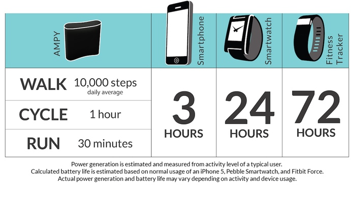
but did little to back them up with actual data. Plus, their definition of “use” for a smartphone was questionable. For a full summary, you can read our original post.
Reception
As predicted, the performance of Ampy according to its backers is less than stellar:
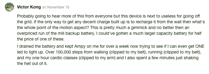
You can dig through the comments yourself, but the general summary is that people are disappointed with the level of motion required to do anything practical with their Ampys.
The response from the Ampy team has been to recommend that their users charge their Ampys from the wall while simultaneously reminding them that they are in fact generating energy as they move.

They also insist that their device generates a large amount of energy in a short period of time. At least it does when they use it:

Since this claim is the first they’ve made with quantified results (instead of “hours of use”), we decided to press them on it and ask for details. This was their response:


Considering other users had used the Ampy on 32km runs and gotten less than a minute of phone charging, we thought that it could be a case of “you’re holding it wrong” and gave them a chance to demonstrate correct use:

They’ve posted no such video.
When setting out to write this review, I thought I might try mounting the Ampy to a paint mixer to see exactly what extreme amount of motion is required to get any use out of the device, but it’s kind of a moot point. If marathon runners can’t get any use out of it, normal users won’t be able to either. Besides, Ampy seems to have backed off their original semi-quantifiable claims and resorted to a Newspeak level of propaganda reminding their users that the device is technically working even if it’s not providing any real benefit:


App
But if you want to see how much you’re generating, why not just use the bundled Ampy+ app? At the launch of the campaign, Ampy claimed that their device would also double as a fitness tracker since the bundled app can display the amount of energy generated and therefore the amount of activity of the user. This could be a good shortcut for a reviewer like me trying to rate performance, but like the Ampy device itself, the app seems to deliver on its promises in theory, but not for any practical purposes.
When I first got the Ampy+ app, I looked for a way to pair it with my Ampy device. The Kickstarter campaign never claimed that there was any kind of bluetooth connectivity, but seeing how the app was supposed to measure the amount of energy generated, it was an easy assumption to make.
Instead of getting measurements directly from the Ampy, the app functions using the phone’s accelerometer. The basic assumption is that if the Ampy is strapped to your hip or in your bag and your phone is in your pocket or strapped to some other part of your body, there should be some correlation between the amount the phone moves and the amount of energy Ampy generates.

Really, all the app is doing here is displaying the activity numbers already produced by the iOS Health app:

And applying some kind of algorithm to it to produce “minutes” of battery life. Given that the app never even asks where the Ampy is located on the user’s body, it’s impossible to believe that these numbers have any relation to reality. It even provided me with “energy generated” numbers retroactively for activity that took place before I received my Ampy
Besides that, the app can help translate the status LEDs on the front of the Ampy device to “hours” of phone life (if the user tells the app what the Ampy LEDs are showing) as well as provide a “forecast” of when the phone’s battery is going to die. I’m not sure how the forecast is generated, but at time of writing, it’s telling me that I have 2 hours of phone life left at 43% battery. And that 4pm is two hours away from 3:25:
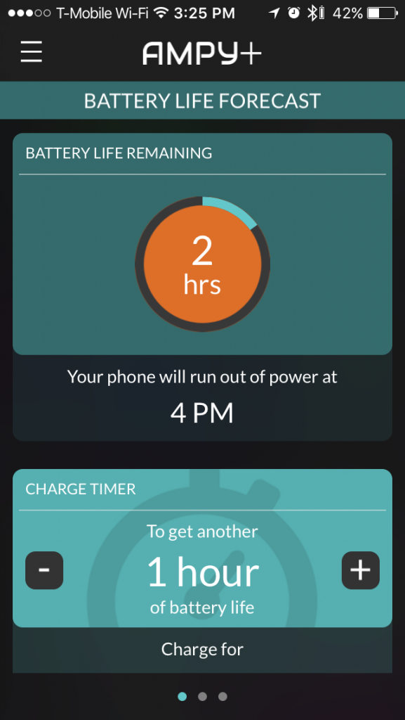
If you’re interested in learning more about the app, it’s free to download, and given that it doesn’t connect to the Ampy at all, you can enjoy all of the benefit it has to offer whether you bought one or not.
Teardown
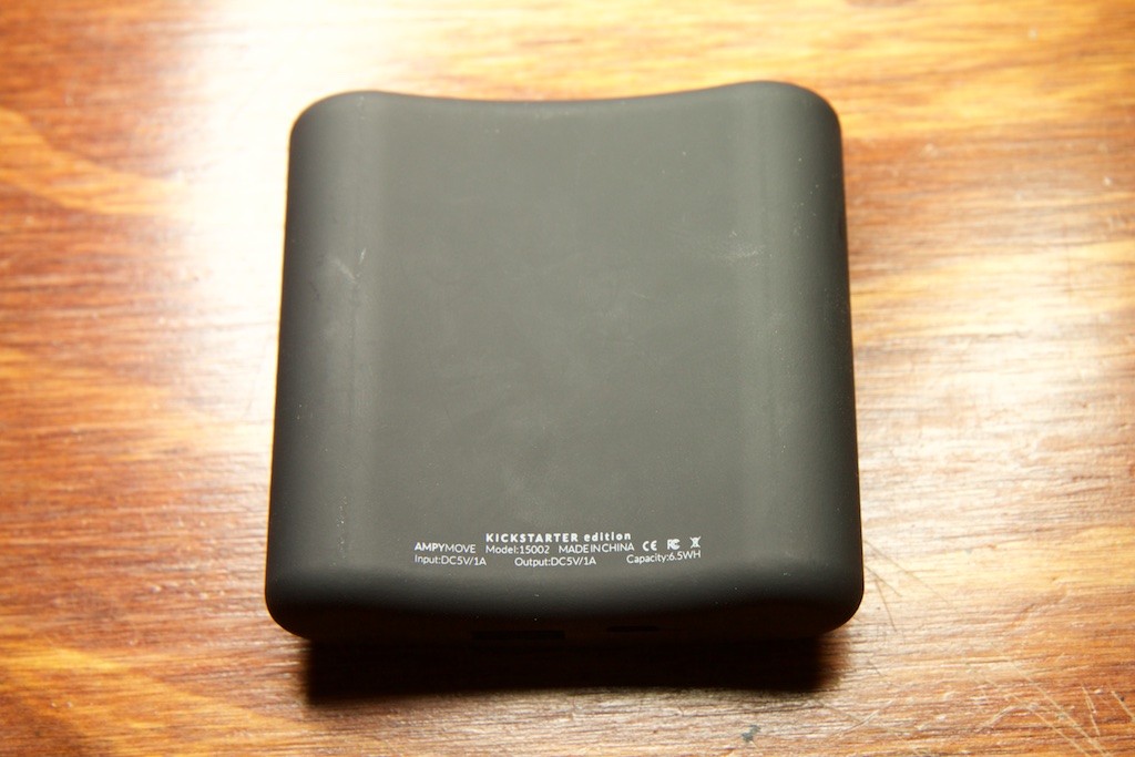
Without doing any real world performance tests, I can already say based on the overwhelmingly negative reviews that this device does not perform a useful function. Indeed, even in a worst case scenario where the user must charge it from a wall plug, it weighs 140 grams, is bulky, costs $100, and still only stores 1800mAh which is less than a $13 Anker battery on Amazon. Even as a fitness tracker, it’s a pretty useless device considering that all of the fitness tracking functionality is contained entirely within the free app (and by extension in iOS itself).
So if it’s not a very useful device, why not just stop the review here?
A smartphone is a hugely power hungry device. With multi-core processors and more ram than the average gaming desktop computer from a decade ago, it’s no wonder that an energy harvesting device will have trouble keeping a phone going. It could be that Ampy Move is just a gadget designed to draw attention to a new energy harvesting technology that could work in a plethora of low-power connected devices like wireless sensors or beacons. Indeed, the Ampy team recently raised $875,000 in VC money to miniaturize their technology for use in wearable devices.
With over twice the money raised from VCs than Kickstarter backers, it should be interesting to see if there really is any “secret sauce” to the Ampy Move or if it just used the momentary success of its Kickstarter to hoodwink some investors.
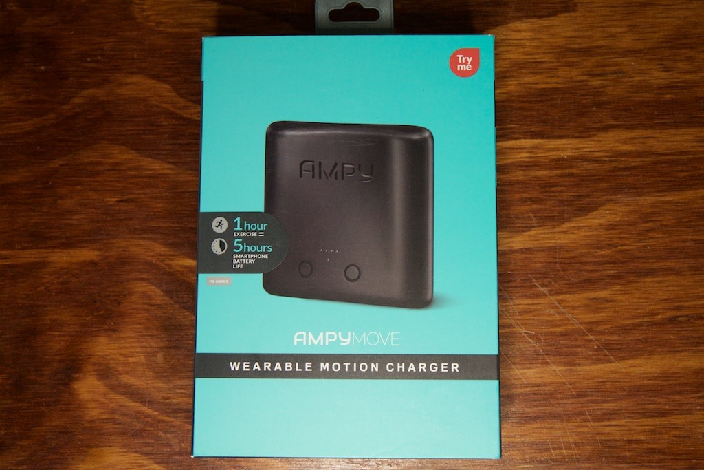
Packaging
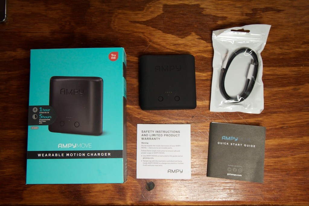
The presentation of the Ampy is excellent. The box is attractive and even includes a fold out section with a magnetic clasp that lets a customer see the device itself and even demo it while it’s inside the box (more on that later). The only other functional thing in the box is a micro USB cable. All of the arm straps offered for Ampy are sold separately.
Appearance and function
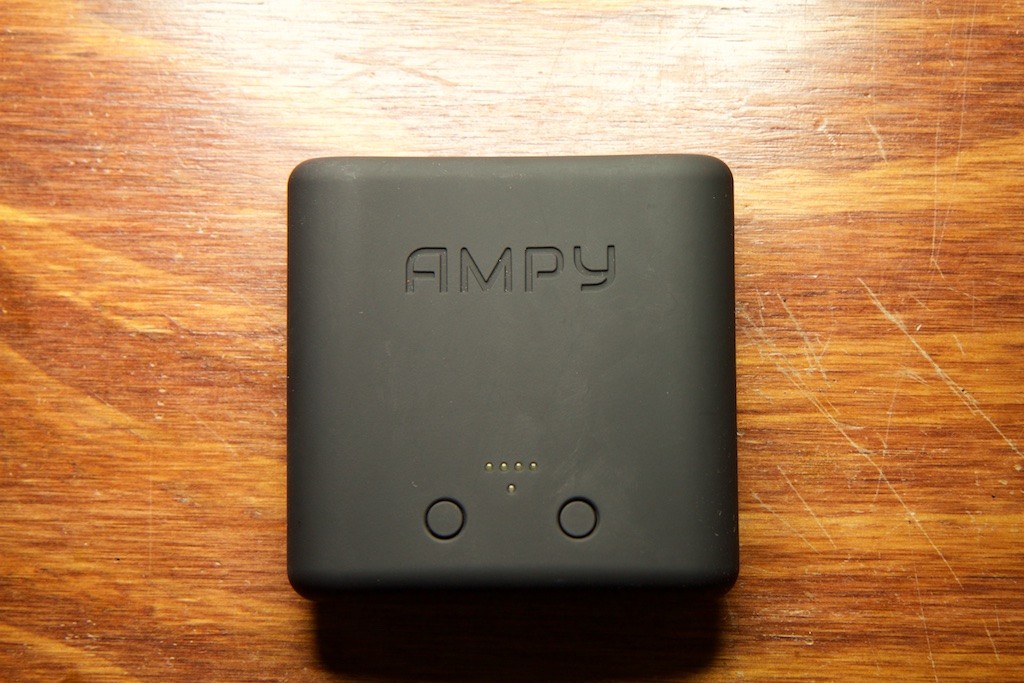
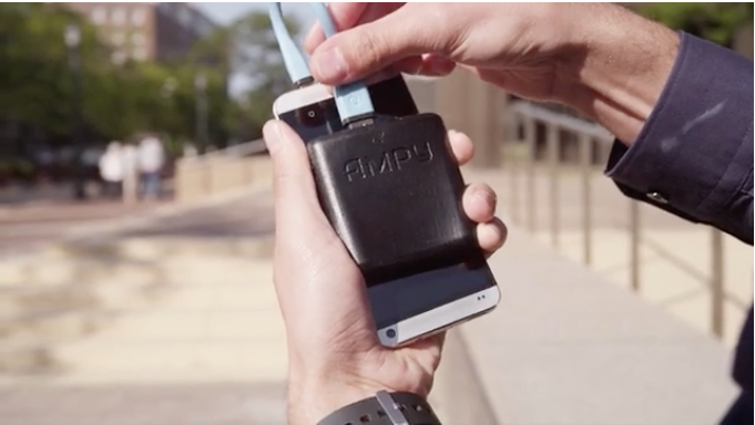
The Ampy is a very attractive device. It’s coated in a rubbery plastic and is ultrasonically welded together meaning that there are no screws visible from the outside. It feels sturdy in the hand (if a little heavy).
When shaken, the Ampy has a definitive orientation. You can feel the energy harvesting masses sliding around inside. When held correctly, the weights seem to bounce off springs; when inverted, the weights smack into the top of the housing. The Ampy team reiterate multiple times in the comments section of their campaign that the device must be held a certain way to function, and I’m guessing this is what they’re talking about.
One thing not obvious from these pictures is that the Ampy is fairly magnetic. A quick test shows that it’s able to hold its own weight when hanging magnetically below the steel bar of my desk lamp. I also noticed that my iPhone’s compass needed calibration after being held in a manner similar to what is demonstrated in the campaign video.
Pressing the left button will illuminate some number of the four white LEDs to indicate the level of battery life and pressing the other button while shaking Ampy will demonstrate the energy being generated in real time:
It’s a gimmick, but it’s a pretty clever one especially since it’s accessible from the little window in the packaging. A great feature for prospective buyers at Best Buy.
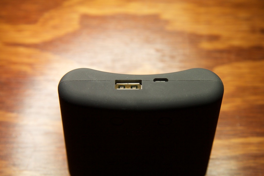
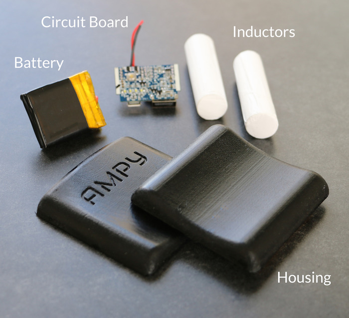
Inside
Due to its ultrasonically welded enclosure, there are no screws or anything to remove when disassembling the Ampy. I had to resort to using a small saw to start a cut on one of the corners. Then a flat head screw driver and some prying action got it apart fairly easily:
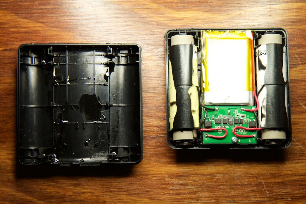
The inside of Ampy is a two PCB construction where one board holds the LEDs and buttons for the front interface and the other holds the remainder of the electronics.
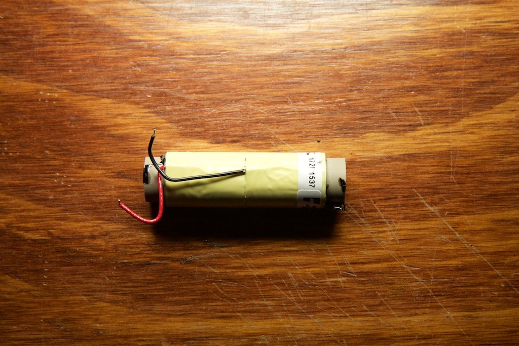
Battery
The battery is nothing remarkable. Just a standard-issue lithium polymer cell with an integrated protection circuit. The only interesting bit about the battery is that the box and battery don’t agree on its capacity:
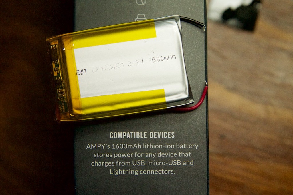
I guess you get 200mAh for free!
The boring stuff
While there may be some interesting circuitry responsible for the energy harvesting aspect of Ampy, a lot of the circuit is there to do basic house-keeping jobs such as charging the battery over USB and displaying the battery life on the front LEDs.
Front display
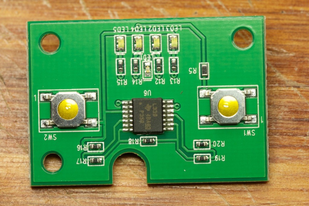
The front display contains an LM339 comparator from Texas Instruments. This chip is responsible for the indicator LEDs. Pressing the left button passes the 5V generated from the main PCB to the comparator to power it up. It then compares the battery voltage to four different levels generated by a simple resistor divider and lights up the appropriate LEDs. This means that the battery levels that the four LEDs indicate are programmed by the physical resistors (R16-R20) soldered to the PCB.
Estimating the capacity of a lithium polymer battery by reading its voltage doesn’t usually give great results. As a lithium battery depletes, its voltage changes at different rates. As you can see in the following graph, there is a very dramatic shift from 0-40% discharged, but a much smaller change from 40-80%. Inside that range, very small voltage changes can have very dramatic implications for the remaining battery life:
Also shown in the graph is how much the rate of discharge (measured in the unit “C“) can affect battery voltage. Without knowing the discharge rate, a 40% depleted battery at 2C might look a lot like an 80% depleted battery at 0.5C.
These problems could possibly explain the phenomenon some users have reported where a seemingly dead Ampy will suddenly have an extra LED of charge:
When the Ampy stops charging a phone, the discharge rate drops to near zero which causes the apparent capacity to jump enough to light up the first LED.
A more accurate battery “fuel gauge” would take into account the current drawn from the battery over time along with the voltage and in some cases even the ambient temperature and age of the battery. It’s pretty clear that the battery gauge on the Ampy is not meant to provide precise battery life information, but is instead the reasonable result of a tradeoff between complexity and cost. Still, it does provide information which some users may find useful.
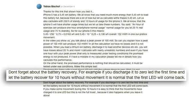
Main PCB
The main PCB contains two large components on either side along with a line of five integrated circuits. Interestingly, all five of these ICs are made by Linear Technology. It’s rare that an entire board will use components from the same manufacturer, but it did make it easier to identify them. I had trouble identifying the chip on the far left from its markings alone, so assuming it was like the others, I plugged its dimensions into Linear’s part finder and found it.
The parts and their functions are as follows:
LTC3539
The LTC3539 is a boost converter. It can take a low voltage and produce a higher voltage. In this circuit, it takes the 3.7V from the battery and generates the 5V necessary to charge a phone over USB. When not charging, it’s also used to power the battery indicator LEDs. Interestingly, it’s always running even if the LEDs are switched off and a phone isn’t connected. This drains a bit of power from the battery, but measurements indicated just 140uA for the entire circuit which would take over a 500 days to fully deplete the battery.
LTC1540
The LTC1540 is a super low power comparator with a built in voltage reference. Its only purpose in this circuit is to compare the battery’s voltage to some fixed voltage and shut off the LTC3539 when the battery drops too low. Presumably this component is in place to prevent the battery from draining too much. As lithium polymer batteries drop below 3V, they become permanently damaged and lose capacity. The inclusion of this part is a bit of a mystery though as the battery’s integrated protection circuitry should prevent it from discharging too much anyway.
LTC4088
The LTC4088 is a run-of-the-mill battery charger IC. It accepts 5V from the micro USB connector and steps it down to the battery’s voltage with a rated 95% efficiency. This part is only used when charging the battery over USB.
LTC4413
The LTC4413 is a set of “ideal” diodes. A diode is a circuit element that will only allow current to travel in one direction. A typical diode will produce a voltage drop as this current flows, but these “ideal” diodes use active circuit elements to reduce that voltage drop as much as possible and improve efficiency. In this circuit, the diodes safely combine the current coming from USB and the energy harvesting circuit into a single stream that charges the battery.
The interesting stuff
With all of that out of the way, it’s time to explore the energy harvesting circuit. Throughout their campaign and comments, the Ampy team have reiterated that there is something really novel about their tech:

Using inductors to generate an electric current is nothing new and brings up memories of those terrible shaking flashlights from the late-night television commercials. When compared to one, the Ampy team promised that their device was something different:


All this talk of proprietary inductor technology coming from three PHD candidates in the field of materials science lead us to believe in our previous review that these guys might have something really unique. We were wrong.
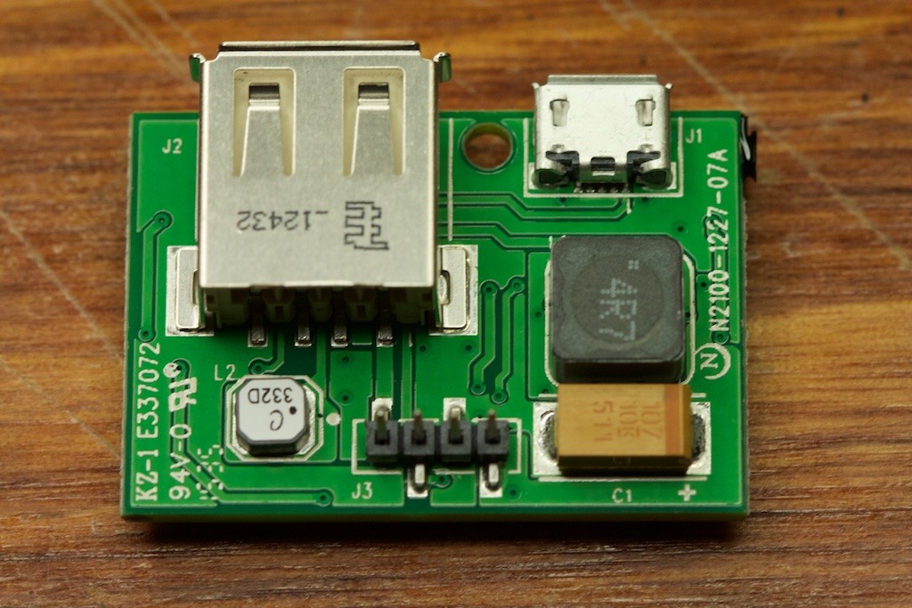
Harvesting circuit
We were right about one thing though. Energy is generated by moving a magnet through an inductor not unlike a shake flashlight. As we explained before, as magnetic fields move through coils of wire an electric current is generated. The only questions are what shape is the coil and what do you do with the current after it’s generated?
The energy harvesting circuit consists of two IC components. Each inductor has its own MB16-STP rectifier which efficiently converts the AC current coming from the coil to a DC current. Once the current is DC, it’s passed to yet another Linear part, the LTC4071. This chip is a high efficiency battery charger designed for charging a battery from “low current, intermittent or continuous charging sources.”
So, that’s really all there is to the circuit. The AC current is rectified to DC and then passed to an efficient charger. No magic here. Just using parts as recommended by their manufacturers.
So what about their “patent pending inductor technology”?
Inductors
We joked before that the Ampy inductors as displayed in their campaign looked like pieces of chalk:
In reality, they’re not so pretty:
Each inductor contains an incredibly powerful neodymium magnet with some foam padding on either side:
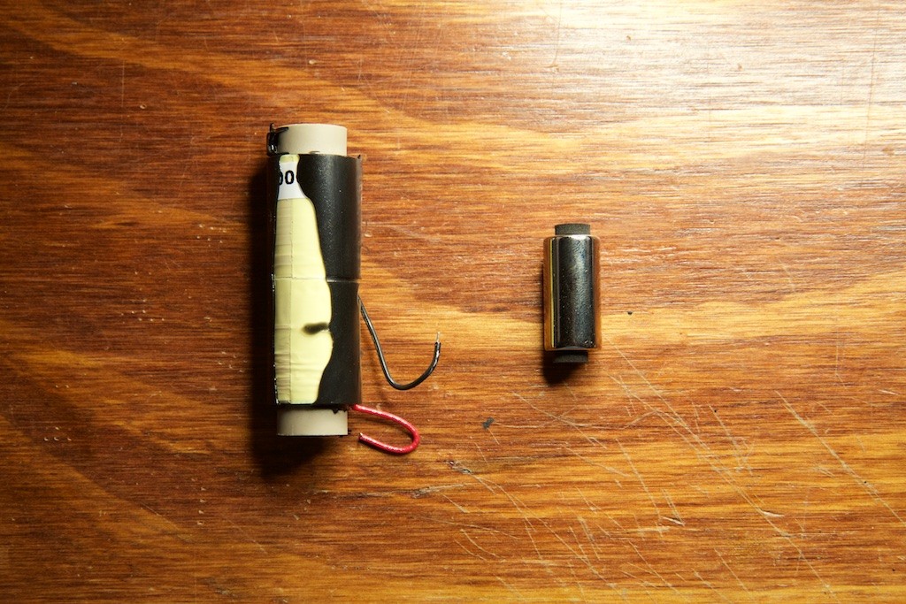
The magnet is allowed to slide around freely inside the inductor, but when the Ampy is held vertically in the correct orientation, an additional magnet prevents it from hitting the bottom of the enclosure:
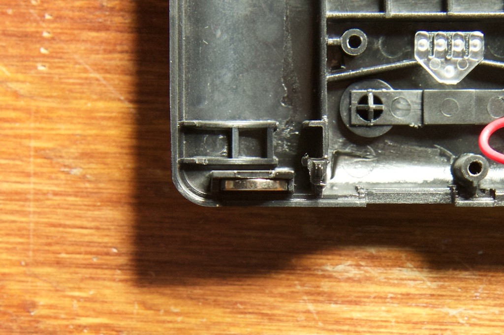
The use of a magnet here was an interesting decision as its fields will act to cancel out some of the fields provided by the sliding magnet. Perhaps the Ampy team determined that it didn’t make too much of an impact on performance and was a fair trade off given the elegance of a magnet over springs (which would have to be made from something other than steel).
Okay, so we have a magnet moving inside an inductor. Still nothing too amazing here. Let’s look at the inductor up close.
The inductor has an unknown manufacturer’s logo and the part number AM-2000-2-2-L printed on a label, but I was unable to find any results for such a part on Google. It’s likely that the part number is generated from the specific properties of the coil (2000 may stand for “2000 turns of wire”), so any data sheets indexed by Google won’t have this precise part number listed.
Removing the yellow tape around the tube revealed a pretty unremarkable inductor:
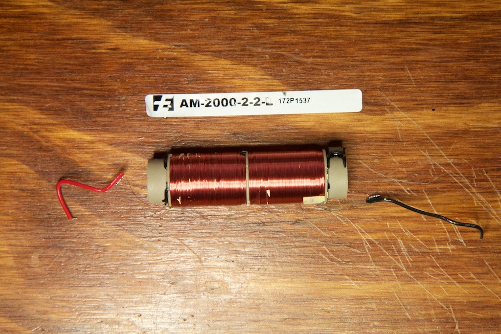
From what I can tell, it’s just some thin magnet wire wrapped around a plastic tube.

Yep. That’s exactly what it is. A thin piece of magnet wire wrapped several thousand times around a plastic tube.
Performance
Maybe there’s something I’m missing here. Let’s see how this thing performs.
While trying to determine if they’re “doing it right,” many backers in the comments of the campaign have explained methods they’ve used for gauging the performance of their Ampy. This usually involves discharging the Ampy until it is totally dead and then shaking it to see how much it will charge a phone before it dies again. There are a lot of things wrong with this method. Firstly, when in deep discharge, driving large amounts of current into a battery will damage it. Because of this, many battery charging ICs reduce current flow into the battery when it’s at a low voltage. Also, battery chargers tend to be less efficient when charging deeply discharged batteries.
You can’t blame the backers though. With such an unreliable battery gauge, there really isn’t another way to measure performance. That is, unless you tear the Ampy apart.
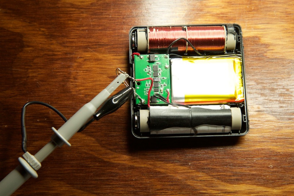
In an attempt to get a ballpark figure for the performance of the Ampy inductors, I placed a small 5 ohm resistor (it’s actually two 10 ohm resistors in parallel) in series with an inductor. By measuring the voltage across this resistor, I can determine the current flowing through it. Because the energy harvesting circuit consists of only a rectifier and a shunt charger, the current passing through this inductor will equal the current flowing into the battery. Full disclosure: by placing this resistor in series with the circuit, I am negatively affecting performance, but given the low current levels present in the circuit, the impact should be small.
I also charged the battery to 3.7V to place it right in the sweet spot of high speed charging.
The setup looked like this:
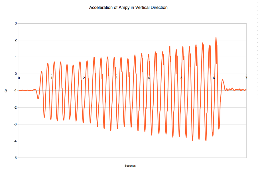
For my test, I shook the device vigorously for a few seconds. Speaking qualitatively, I could feel the magnets almost bottoming out on the “spring” loaded bottom which I suspect is about as vigorous an activity as anyone is going to perform while wearing an Ampy. Quantitatively, I generated this acceleration graph with my iPhone which I held tightly against the Ampy:
During this test, the voltage across my resistor looked like this:

Each bar going left to right represents 0.2s of time, so the entire graph represents 2 seconds. As you can see, I was shaking the Ampy at 4.849Hz which means I completed about five up and down shakes each second.
In order to determine the amount of current delivered to the battery, we need to convert from AC current to DC current. This can be done by taking the Root Mean Square or RMS of the waveform. The RMS voltage as determined by my oscilloscope’s software is 43.28mV. Using Ohm’s law with the 5ohm resistor gives us an average current of 8.6mA. Because this was only measuring one of the two inductors, the actual current delivered is probably somewhere around 19-20mA.
Assuming I kept this up constantly and there were no other losses anywhere in the system, charging an 1800mAh battery with 20mA of current would take roughly ninety hours. Even assuming I’m low-balling my measurements, the battery charger IC is only rated for a maximum 50mA:
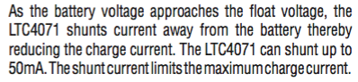
This means that in the absolute best case, the Ampy will require 36 hours of activity to fully charge its battery. It’s uncertain what level of activity would be necessary during those 36 hours, but if my measurements are any indication, you need to move quite a bit.
Correction: The LTC4071 can source more than 50mA to the battery, but when provided any more current than that, it is unable to prevent the battery from being overcharged and potentially damaged. Considering the recommendation to fully charge the Ampy from the wall before starting out, it’s likely the Ampy team designed it with this in mind. The LTC4071 is configured with an R_in of 54 ohms which means it can accept a voltage of up to 6.9V from the inductors without causing damage.
Proprietary technology?
I was fairly certain after my initial review that the Ampy would perform about as poorly as it has, but I was looking forward to finding something novel about it this time around. After all, these guys managed to get an additional $875,000 worth of funding to further develop their technology. Certainly somewhere along the way, someone must have asked where their value-add is. But where could it be? Is it using a bridge rectifier designed for rectifying AC current into DC current to convert AC current into DC current? Maybe it’s using a battery charger designed for charging a battery with intermittent current sources to charge a battery with an intermittent current source?
Could it be their inductor technology which uses special wire that’s conspicuously similar to this spool from bulkwire.com?

Sarcasm aside, this really is a perplexing result. I could understand a project where a promising and novel technology is proposed only to find that it’s too difficult to manufacture, or too expensive, or too fragile, or not as effective as originally thought, but the Ampy story is different. Unless the product underwent some major design overhaul since their campaign and still delivered with few delays, it really looks like this team took a fairly well-understood and poor solution to a problem and pitched it as something extraordinary.
We’ve seen people pitch readymade solutions as new before, but this isn’t that either. The Ampy team went through the effort to create an entirely new product based on old ideas that have already been shown not to work while adding nothing novel in the process. Given their predilection for Linear parts, I’m a little curious if they just went through a Linear Tech catalog and circled all of the parts that mentioned “energy harvesting battery charger.”
Ampy went to great lengths to never promise concrete results to their backers, so it comes as no surprise that the device performs only to the most generous standards. I can only imagine how they explained their “proprietary technology” to their investors though and what those investors are going to say when they discover the man behind the curtain trying to squeeze a coil of wire into a smartwatch.
![]()